Intelitek Pneumatic Technology curriculum introduce students to the principles of pneumatics and pneumatically controlled systems commonly used in automated manufacturing environments.
Using Pneumatic simulation software, trainees create, modify, operate and observe simulated industrial grade pneumatic and electro-pneumatic devices and circuits. Students will connect different components, change physical parameters and observe system responses.
Curriculum
Pneumatics 1 enables students to design basic pneumatic circuits. Applied science experiments are used to demonstrate the physical principles of fluid power.
Students create, modify, operate and observe simulated pneumatic and electro-pneumatic devices and circuits. Students can mount and configure virtual and real components in order to create a variety of applications. Students connect different components, change parameters and observe system responses.
Students design solutions for industrial pneumatic applications with emphasis on real industrial concerns, such as power losses across components, system overheating and optimized pneumatic power.
Course Outline
- Activity 1: Introduction to Pneumatics
- Activity 2: Atmospheric Pressure and Vacuum
- Activity 3: Atmospheric Pressure, Vacuum and Mechanical Work
- Activity 4: The Double-Acting Cylinder
- Activity 5: 3/2 Valves
- Activity 6: Controlling a Piston with PBs
- Activity 7: 5/2 Air-Operated, Air-Returned Valve
- Activity 8: 5/2 Air-Air Valves
- Activity 9: Laws of Gases I
- Activity 10: Laws of Gases II
- Activity 11: 3/2 Air-Operated, Spring-Returned Valve
- Activity 12: Spot Welding System
- Activity 13: 3/2 Roller Valves
- Activity 14: The Punch – A Semi-Automatic System
Pneumatics 2 covers a range of advanced pneumatics topics, including timing diagrams and the logic functions AND and OR.
Course Outline
- Activity 1: Getting Started
- Activity 2: The Logic Function AND
- Activity 3: Implementing AND in a Pneumatic Circuit
- Activity 4: The Toggle Valve
- Activity 5: Using AND to Build a Fully Automatic System
- Activity 6: The Logic Function OR
- Activity 7: Implementing OR in a Pneumatic Circuit
- Activity 8: Circuit with Two Double-Acting Cylinders
- Activity 9: Sequential Cycle
- Activity 10: A Delay
- Activity 11: Sequential Control with a Timed Delay
- Activity 12: Opposing Control Signals
- Activity 13: Timing Diagrams
- Activity 14: Using a Single Pilot Valve to Prevent Opposing Control Signals
- Activity 15: Using A Single Pilot Valve in a Pneumatic Circuit
Pneumatics 3 enables students to mount and configure components on the panel in order to create a variety of applications. Students connect different components, change physical parameters and observe system responses. The combination of software and industrial equipment allows students to test and troubleshoot simulated circuits before hardware connections are made
Course Outline
- Activity 1: Getting Started
- Activity 2: Building a Basic Electrical Circuit
- Activity 3: The 5/2 Solenoid-Spring Valve
- Activity 4: The 5/2 Solenoid-Solenoid Valve
- Activity 5: Magnetic Switches
- Activity 6: Implementing the Logic Function AND
- Activity 7: Implementing the Logic Function OR
- Activity 8: Implementing the Logic Function NOT
- Activity 9: Sequential Operation
- Activity 10: The Relay
- Activity 11: Unlatching a Relay
- Activity 12: Building a Fully Automatic Circuit
- Activity 13: Adding a Delay Using an Electric Timer
- Activity 14: Unlatching a Fully Automatic Circuit
- Activity 15: Measuring Cylinder Speed
Hardware Training Kits
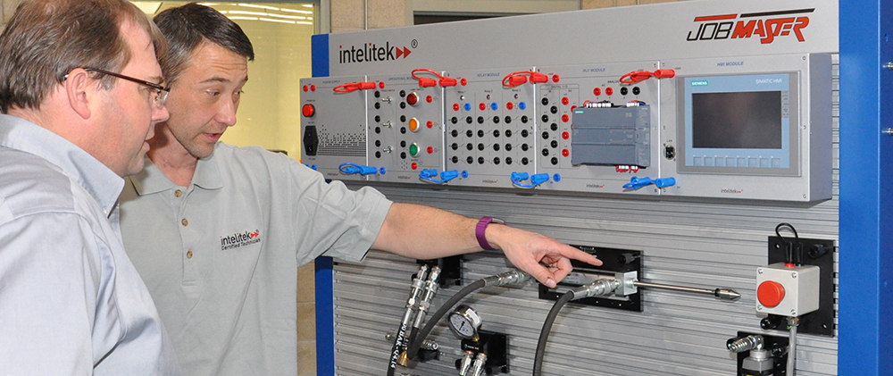
The training is supplied with a wide assortment of industrial grade pneumatic components. Students can mount and configure components on the JMTS panel in order to create a variety of applications. Students can connect different components, change physical parameters and observe system responses. The unique combination of software and industrial equipment allows students to test and troubleshoot simulated circuits before hardware connections are made.
Required JMTS Training Station Electronics Units
- JMTS – Power Supply Module
- JMTS – PLC Module
- Conditioning unit: pressure regulator, pressure gauge, water trap, air filter, lubrication unit; max. inlet pressure: 16 bar; pressure range: 0-8 bar
- 5/2 double air pilot valve (5/2 air-air control Valve)
- 3/2 mushroom push button (3/2 push button valve) (x2)
- 3/2 lever valve (3/2 manually operated valve, toggle valve)
- 3/2 double roller lever valve (3/2 roller valve)
- 3/2 pneumatic valve (3/2 air-spring control valve)
- AND gate
- OR gate
- NOT gate
- Double-acting cylinder
- Manifold
- T-connector (x4)
- Connector (x4)
- Quick-coupler
- Tubing
- Double-acting cylinder
- 5/2 double air pilot valve (5/2 air-air control valve)
- Single air pilot valve (x2)
- 3/2 double roller lever valve (3/2 roller valve)
- Pneumatic time delay valve
- Manifold
- 5/2 double solenoid valve (5/2 sol-sol control valve) (x2)
- Inductive proximity sensor (x2)
- Magnetic sensors (pair)
- Banana plug cables (14 total), assorted colors and lengths: red, black, gray; 610 mm (24″), 1220 mm (48″)
PneuMotion
PneuMotion software is a computer-aided design tool that teaches students how to design and operate pneumatic and electro-pneumatic circuits. PneuMotion enables the study of pneumatics principles and technology. The software’s HMI animation provides an accurate working simulation of pneumatic devices and circuits.
Users can change the default parameters of the pneumatic components, such as piston extension and retraction, speed and timer set point. Software algorithms adjust the system’s response to present a realistic pneumatic system response.
In addition to simulation of virtual circuits, PneuMotion can control actual electro-pneumatic circuits. When connected to the JMTS training panel, the software provides on-line graphic tracking of circuits in operation. (Requires computer interface control unit.)

