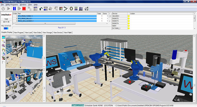
OpenCIM Offline is the simulation version of OpenCIM. Users can design and run an unlimited variety of CIM or FMS cells in simulation mode, but cannot operate or control actual CIM cells.
OpenCIM Intro is a basic version of OpenCIM Offline. Users can run all the demo CIM systems included in the software and can perform manufacturing management (such as part definition, storage management, MRP, reports), but cannot design or modify CIM cell configurations.
OpenCIM software provides a comprehensive solution for the study and practice of CIM methods and operations:
– OpenCIM gives students experience and knowledge in the concepts, uses and interconnections of the various software modules that comprise a CIM system.
– OpenCIM allows students to gain practical experience in translating theoretical manufacturing methods and processes into actual CIM applications.
– OpenCIM enables students to use and study components and subsystems individually as well as the entire integrated CIM system.
– OpenCIM includes enhanced optimization functions and performance analysis to support studies in industrial management, operations research, management sciences and related fields.
OpenCIM incorporates the latest advancements in CIM and software technologies:
– OpenCIM is an enterprise resource planning (ERP) tool. It combines a number of CIM cell and station management modules: MRP for defining parts, machines and processes, customer, purchase and production orders; inventory control and tracking; scheduling and dispatching; report generation.
– OpenCIM implements manufacturing execution system (MES) technology. It integrates real-time information with the system’s PC-based database, and maintains online communication with all subsystems through a LAN, a lab network or the Internet.
– OpenCIM includes a 3D solid model graphic display module that dynamically and accurately simulates the CIM components and processes. It provides both online graphic tracking of the manufacturing processes and off-line simulation that allows students to test procedures before executing an actual production run. Students can also design virtual CIM cells and experiment with CIM and workcell configurations that are not actually available in the CIM lab.
OpenCIM Web viewer enables access to CIM manager via the Internet and allows users to monitor CIM cell operations in real time from remote locations. Using internet browsers, users can view realtime reports generated by the CIM manager, remotely track live production cycles in the 3D graphic display, and view details of current CIM cell status.
OpenCIM’s open architecture enables the integration of various hardware and software components, making it easy to expand and customize the CIM system.
Integration of systems and technologies
– Supports numerous elements and manufacturing processes.
– Material storage and feeding (ASRS, feeders, palletizing racks).
– Material handling (robots, conveyors, slidebases, pneumatic transfer units, positioning tables, vises, end effectors and tool changers).
– Automated manufacturing and fabrication (assembly, glue dispensing, screwdriving, welding, grinding/deburring; hydraulic pressing).
– CNC machining (turning, milling, engraving, routing, automatic tool changers).
– Pneumatic and hydraulic systems (manipulators, feeders, presses)
– Identification, detection and tracking (barcode scanning, pallet tracking, sensors, switches).
– Quality control (machine vision, electronic calipers, coordinate measuring machine, laser scan meter, electronic height gauge).
– Process control
– Programmable logic controllers (PLC)
Open software architecture
– Object oriented technology enables user modifications and integration with other applications.
– Interfaces with a variety of machines and robots by means of device drivers (small interface programs that translate and transmit messages between the CIM manager and the machines at CIM stations). Device drivers are supplied with system. User can create and modify device drivers to suit any machine type or model.
– Interfaces with third-party software tools such as MRP, ERP, CAD, CAM, SQC (statistical quality control, CRM (customer relationship management), PDM (product data management).
– Stores all data in standard industrial database format, allowing easy access and manipulation on any level. Data files can be read by any Windows application (e.g., Excel, Access, MS-SQL) and exported to any other application. Easily imports and uses data files from external applications.
– User can write applications (e.g., in Java, Visual Basic, C++, C#) that will monitor real-time communication and display the data (graphically or statistically).
Internet access
– CIM Web viewer enables access to CIM manager via the Internet and allows users to monitor CIM cell operations in real time from remote locations.
– Using Internet browsers users can view realtime reports generated by the CIM manager, remotely track live production cycles in the 3D graphic display, and view details of current CIM cell status.
– Simultaneous Internet access by multiple users
Real-time communication
– Multi-level, hierarchical communication network design, based on commonly used industrial communication networks; allows user to practice and understand different communication networks and protocols.
– Uses TCP/IP protocol for real-time communication between the CIM manager and device drivers: LAN (Microsoft, Novell or any other Windows-compatible network); WAN (CIM manager PC or any station manager PC can be operated from any location on the network, such as a remote classroom).
– Uses additional communication protocols: RS232 (connects PCs to machine and robot controllers); I/Os (connects external inputs/outputs to machine and robot controllers); Field bus (AS-I bus or PROFIBUS, optional)
Modes of operation
– Full simulation mode: software runs without any hardware or user intervention. Device drivers notify the CIM manager when operations have been executed
– Simulation with manual control: software runs without any hardware, but the user interactively emulates the hardware by using device driver control panels.
– Mixed mode: some components actually operate, while others are simulated. The simulation is based on data that predicts and defines the duration of processes. Device drivers are used to simulate operation of inoperative or missing components.
– Full online mode: Software runs the system according to user programming. Device drivers operate the workcell according to orders from the CIM manager.
– Stand alone station operation: Individual stations and many components (e.g., robots, CNC machines, quality control devices) can be programmed, operated and controlled as stand-alone systems by means of their own software or the system’s device drivers.
– User interface is identical in all modes of operation, which reduces the time and effort required for software familiarization
Dynamic 3D Graphic Simulation
– Fully functional, dynamic 3D simulation module.
– Accurately simulates operations and movements of machines, robots and peripheral axes, including components such as safety shields, chucks and spindles.
– Accurately simulates part transportation and manipulation, including movement of pallets on conveyor and supply of parts from storage cells and feeders.
– Accurately simulates manufacturing processing, including milling, turning, engraving and welding.
– Parts change color to reflect different stages in processing.
– Accurately simulates the physical environment of the CIM cell.
– Simulation speed can be defined by the user
– Three graphic display windows can simultaneously display three different 3D views of CIM cell.
– View control: zoom in and out, rotate (pan), view from above, below and any angle in between; camera redirect (reset camera’s focal point), drag camera (moves viewing area).
– Follow-me camera: automatic and continuous camera redirect; useful for following a robot gripper or any moving object, such as a workpiece undergoing processing.
– Lighting and shading control.
– Enables more efficient use of CIM laboratory. Keeps equipment free for actual, online execution of applications and production cycles.
– Improves comprehension of CIM management and manufacturing processes by viewing 3D graphic dynamic on-screen simulations.
– Enables testing of the effect of various production strategies, or various shop floor layouts, on the behavior of the system.
– Allows programming and operation of the CIM system without causing damage to actual equipment or disrupting operation of the actual CIM cell.
– Allows testing and debugging of programming before online production is initiated.
– Enables experimentation with CIM cells in which some components actually operate while others are simulated.
– Allows work with virtual CIM workcells that do not actually exist.
Virtual CIM cell setup
– User can design, create and modify CIM cells and components.
– Cell setups can represent actual installations or virtual cells.
– Interactive point and click object placement and property definitions.
– Object library includes: 10 robots; 6 CNC machines; additional machines and stations (e.g., welding, laser engraving, pneumatic sorting); peripheral axis devices (e.g., conveyor belt, linear slidebase, rotary table); positioning devices (e.g., jigs, XY tables), 5 quality control devices (e.g., machine vision, CMM, LSM, calipers), sensors and I/O devices; 13 storage devices and feeders; conveyor and PLC control unit; tables, workbenches, computers.
– Conveyors and tables automatically created according to user-defined width/length dimensions.
– Robots can be mounted on table, slidebase or gantry.
– Any quantity of any part can be defined for storage devices and feeders.
– Any shape or size can be defined for parts.
– External CAD software can be used to design new 3D objects and assembled parts for manipulation by robot and other devices in workcell. Includes utility for importing 3D object files
Data acquisition and visualization
– Online 3D graphic tracking shows movement of robots, machines, parts, conveyor and other CIM elements in a dynamic simulation of the shop floor.
– Gantt charts present planned and actual scheduling of manufacturing processes.
– Status views allow user to track production through eight screens that display data such as manufacturing orders; status of storage locations; current activity of all machines, robots and devices; status of pallets; log of all transmitted messages, etc.
– Report generator lets user view and print ten types of predefined reports (e.g., machines, ASRS contents, manufacturing orders), or an unlimited number of own user-defined reports using Crystal or other report generating software.
– DBTool utility allows user to edit database files, repair database files, and save files in DBF or TXT format.
– All data is written and stored in standard industrial database format to enable easy access, manipulation and use by any software application.
– Database files from external applications can be easily imported and used
Advanced (MES) operations
– Enables manufacturing optimization by allowing user to control algorithms used for part dispatching and machine queues. Parts waiting to be processed by machines can be queued according to parameters such as minimum process time, maximum priority, FIFO, etc.
– Includes open source that allows user to add new queue algorithms.
– Enables testing of algorithms, comparison of results, and analysis of system performance. Optimizes use of machines when two machines capable of performing a specific process are both available.
– Alerts user of any malfunction of any CIM component. User can correct the problem and instruct the system to repeat, continue or abort the operation. Disruption in the operation of other CIM components is minimal.
Interface languages
– English
– CIM Manager, Project Manager, CIM Virtual Setup and Storage Manager modules can be easily translated into any user language.

